lead accumulators (and Li-ion batteries)
|
Automatic charger and discharger for small
lead accumulators (and Li-ion batteries) |
|
Back to Stefan's Some technical projects page
Report by Stefan Spännare, July 2006, updated May 2007 and February 2010
Note, print this web-page in landscape mode if the images don't fit into portrait A4.
For more information see the references below.
i. Warning
1. Introduction
2. Data for the charger regulator
Updated!
3. Data for the discharger
4. Advantages and disadvantages with the charger regulator
5. Advantages and disadvantages with discharger
6. Calibration of the charger regulator
7. Calibration of the discharger
8. Building instructions
9. Lead accumulator charger regulator
10. Lead accumulator discharger
11. Power supply 2 - 32 V DC max 2 A stabilized
12. Some images (photos) of the project
13. References
The author makes no warranties that this document is free of errors.
Be careful to use correct charging voltages and currents to the lead
Small sealed lead accumulators should be carefully charged with correct
First the battery is charged at maximum current (for example 0.1·C A). When
The discharger is used to discharge an accumulator without going below
It should be pointed out that lead accumulators should always be charged again
Note, it seems as if this charger regulator is very well adapted also to charge
Note,
the charger regulator can be used also for 6 or 18 V lead accumulators
Data for the charger regulator (lead accumulators):
Charge voltage (12 V acc): 13.00 - 14.00 V; recommended 13.50 - 13.80 V
Charge voltage (24 V acc): 26.00 - 28.00 V; recommended 27.00 - 27.60 V
Charge current (12 or 24 V acc): 0.3 - 2.0 A; recommended 0.1·C - 0.2·C A (*)
Approximate charging time at 0.1·C A current: 15 h
Input voltage from power supply (12 V acc): 19.00 V DC
Input voltage from power supply (24 V acc): 31.00 V DC
(*) Here C is the charge capacity of the accumulator in Ah.
Data for the discharger:
Lowest discharge voltage (12 V acc): 9.00 - 12.00 V; recommended 10.50 V
Lowest discharge voltage (24 V acc): 18.00 - 24.00 V; recommended 21.00 V
Maximum discharge current: 2.00 A; One or two car lamps 12 or 24 V, 10 W recommended
Advantages:
Disadvantages:
Advantages:
Disadvantages:
Read this section through carefully before starting to use the charger regulator.
1. Adjust the current trim potentiometer to the middle position (about 5 revolutions from the end).
2. Adjust the voltage trim potentiometer to the middle position (about 5 revolutions from the end).
3. Adjust the power supply to 19.00 V for 12 V accumulators or 31.00 V for 24 V accumulators respectively.
4. Connect the charger regulator input to the power supply. Note polarity. One LED should light.
5. Connect a load (about 200 mA) to the output of the charger regulator. Three Christmas candle
6. Adjust the charger regulator output voltage to 13.00 V for 12 V accumulators or 26.00 V for 24 V
7. Connect the charger regulator output to the lead accumulator (note polarity) and immediately adjust
8. During the whole first charge process the voltage must be carefully monitored and adjusted to not raise
9. Fine adjust also the current to desired level during the first hour of charging.
10. The charge is finished after about 15 hours at 0.1·C A charging current or when the charge
The voltage and current potentiometers must only be adjusted the first charge time for a certain set of
Read this section through carefully before starting to use the discharger.
1. Connect one car lamp (12 V, 10 W or max 20 W) for 12 V accumulators or two car lamps in series
2. Adjust the power supply to not lower than 10.50 V for 12 V accumulators or not lower than
3. Connect the power supply to the input of the discharger.
4. Adjust the potentiometer on the discharger so the lamps goes from light to completely dark at
5. Connect the input of the discharger to the lead accumulator (note polarity). The lamp(s) should light.
6. The current of the lamp(s) (10 W) is about 0.8 A. So a fully charged accumulator is discharged
When the lamps goes dark the current drops to about 20 mA (after a while). Then the accumulator is
It is quite straight forward to build the charger regulator and discharger on
The charger regulator can be used for both 12 V and 24 V accumulators by
The lead accumulator charger regulator. Circuit layout:
The lead accumulator discharger. Circuit layout:
A power supply 2 - 32 V DC max 2 A stabilized that can be used with the
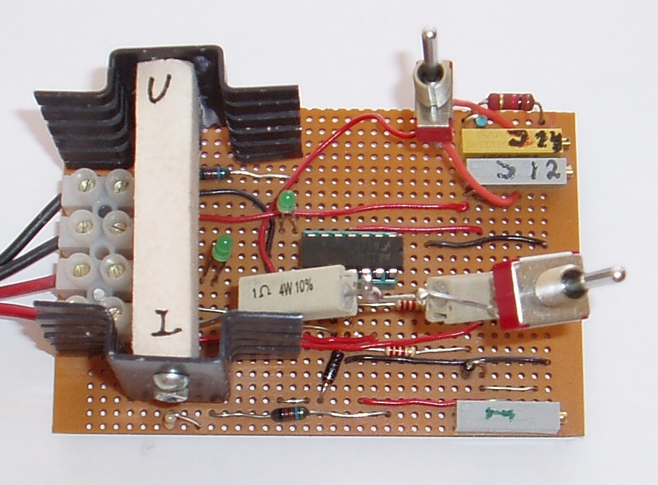
1. The lead accumulator charger regulator. Note the switches for voltage
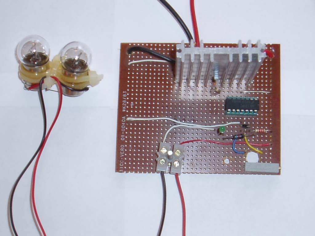
2. The lead accumulator discharger with two car lamps (12 V, 10 W) connected
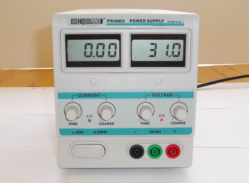
3. The power supply adjusted to 31.0 V.
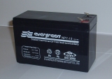
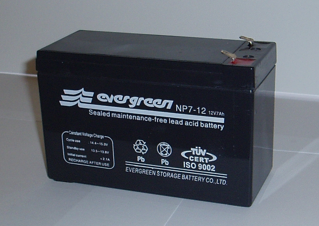
4. A lead accumulator 12 V, 7 Ah.
Some useful data sheets (mostly from ELFA) to download:
Some useful Internet links:
i. Warning
accumulators, avoid short circuit and use high quality components. It is very
important to connect the charger and discharger with correct polarity to the
lead accumulator and power supply otherwise the circuits will be immediately
destroyed. This can be dangerous because lead accumulators produce very
high currents when short circuited.
1. Introduction
voltage and current. Here are described an automatic charger regulator and
an automatic discharger for 12 or 24 V accumulators. An extra power supply
(19 or 31 V DC) is also required. Both the voltage and current are automatic
regulated to desired level and can be used for continuous charging.
the adjusted voltage is reached (for example 13.80 V for a 12 V accumulator)
the current is gradually reduced but the voltage is kept constant.
a voltage that can damage the accumulator. When the voltage drops to the
adjusted voltage (for example 10.50 V for a 12 V accumulator) the current
gradually goes down to zero.
after being used and discharged. They should always be stored fully charged.
2. Data for the charger regulator
Li-ion batteries Under the assumption that the charging voltage is not higher
than 4.10 V (4.20 V at maximum) per cell. See this very good article:
Charging lithium-ion batteries.
if the regulator charge voltage is adjusted to 2.30 V per cell at maximum
(i.e. 6.90 or 20.70 V respectively). As usual the power supply voltage should
be at least 7.0 V above this.
3. Data for the discharger
4. Advantages and disadvantages with the charger regulator
5. Advantages and disadvantages with the discharger
6. Calibration of the charger regulator
It is recommended to have one (or better two) digital multimeter(s) at hand during this process.
lamps (34 V, 3 W each) connected in parallel should work fine.
accumulators respectively with the lamps as load.
the current to not more than 0.1·C A (or 0.2·C A at maximum). Perhaps the switch on the 1 Ohm
resistor must be changed to get desired current. Perhaps this step can not be completed before also
the voltage is adjusted.
above to 13.50 V (13.80 V at maximum) for 12 V accumulators and 27.00 V (27.60 V at maximum)
for 24 V accumulators. This step is very important but can be somewhat tedious.
current goes down below 50 mA (somewhat dependent of the charge capacity of the accumulator).
accumulators. When the desired voltage is reached the current starts to go down and the first LED goes
dark and the second is light. The heatsinks of the transistors become quite hot during the charge
process.
7. Calibration of the discharger
It is recommended to have one (or better two) digital multimeter(s) at hand during this process.
(12 V, 10 W or max 20 W) for 24 V accumulators to the output of the discharger.
21.00 V for 24 V accumulators.
the pre-adjusted voltage.
after about C / 0.8 hours. Here C is the charge capacity in Ah of the accumulator.
almost not further discharged and can be connected to the discharger for several days. The heatsink
of the transistor on the discharger becomes quite hot just when the lamp(s) goes dark.
8. Building instructions
standard laboration cards. The power transistors (BDX 34 C and BDX 33 C) must
have quite large heatsinks. To avoid short circuit and wrong polarity power
diodes (1N5404, 3 A) can be connected to the input and output cables. But
then the voltage from the power supply must be raised with about 1.4 V. It
should be noted that the maximum voltage for the LM 324 IC is 32 V (absolute
maximum ratings).
having a switch (SW1) for each accumulator type voltage. Both voltages must
be calibrated once by the potentiometers. Don't forget to change the power
supply voltage as well. The current adjustment can be the same under the
assumption that the charge capacity for both 12 V and 24 V accumulators
are approximately the same. It can be wise to have two power resistors
(1 Ohm, 4 W) connected in series in the charger regulator circuit. One of the
resistors can then be short circuited by a switch (SW2) to make it possible
to double or half the charge current.
9. Lead accumulator charger regulator
10. Lead accumulator discharger
11. Power supply 2 - 32 V DC max 2 A stabilized
charger regulator. Note, this circuit has not been built and tested but should
work fine anyway. The LM 350 voltage regulator must have a quite large
heatsink. Circuit layout:
12. Some images (photos) of the project
and current selection. The piece of wood stabilizes the heatsinks.
in series as load.
13. References
by STMicroelectronics, December 2001
by STMicroelectronics, October 1999
Author: Stefan Spännare
E-mail: stefan@NOspaennareSPAM.se
(Please remove NO and SPAM before sending)
Latest update: 2010-02-02