"inverted pendulum" with PID-regulator software
|
A very simple and cheap computer controlled
"inverted pendulum" with PID-regulator software |
|
Back to Stefan's Some technical projects page
Report by Stefan Spännare, August 2009
Note, print this web-page in landscape mode if the images don't fit into portrait A4.
This document is based on free information found elsewhere on Internet.
i. Warning
1. Introduction
2. Technical information about the project
3. Download PID-regulator software for the Velleman K8061 I/O-board
!!!
4. Some auxiliary circuits
4.1 Voltage regulators +5, +9 and +12 V
4.2 Inverted pendulum auxiliary I/O interface
5. Building instructions
6. Components and prices for the project
7. Some images (photos) of the project
8. A short video with the pendulum in action
9. References
The author makes no warranties that this document is free of errors.
Do absolutely not use the USB devices, software and circuits described
i. Warning
in this report for professional and continuous use. USB devices can quite
easily hang and the setup should be carefully monitored when used.
Be careful to connect all the circuits and the motor controller with correct
voltage and polarity.
Here is described a very simple and cheap "inverted pendulum" controlled
from a PC with PID-regulator software. Actually I don't know if it deserves
the name "inverted pendulum", but it is an easy and funny way to play around
with a PID-regulator.
Future development: I have the intention to also make an inverted pendulum
on a chart, a Furuta pendulum and a quite small balancing and moving
two-wheel "robot" during the coming year or so. According to different
sources on Internet it is not possible to run a Furuta pendulum with a
simple PID-regulator with good result. Instead the full state equations are
needed. This will be a challenge for me to implement, because it involves some
quite advanced mathematics. I also hope that a simple but high quality 360
degree potentiometer works well as angular actuator for the Furuta pendulum
arm. More advanced angular actuators are so expensive. The balancing robot
needs an accelerometer to stand upright, and it should also be possible to
move around and even turn at the same time as it is balancing. I hope the
Velleman K8061 I/O-board is fast and accurate enough for these purposes.
The pendulum DC motor comes from an defective HP inc jet printer in the
DeskJet 6xx, 7xx, 8xx or 9xx series. It is the motor that drives the inc
cartridge chart back and forth. The motor voltage to the motor controller
should be adjusted to about 18 V. These motors have a stall current of about
3 A. The pendulum arm consists of a 39 cm steel wire with a diameter of 2 mm.
About 1 cm of it is bent to fit to the 1/8" motor axis. As motor axis connection
is used a piece of a cable connection plinth (see the images in section 7
below). The weight at the end of the pendulum arm also consists of a five
unit cable connection plinth with a weight of about 12 g. It is instructive
to change the length of the pendulum arm and the size of the weight with
different PID-regulator values.
As pendulum angle actuator a 10 kOhm linear potentiometer is used connected
between +5 V and ground. A/D-channel 1 of the Velleman K8061 I/O-board is
used via one operational follower on the small auxiliary interface board.
Additional potentiometers and actuators can be connected the similar way to
A/D-channel 2 to 7 if you wish. Then the PID-regulator program C-code must
also be modified. The A/D-channels of the Velleman K8061 I/O-board has 10
bit resolution (i.e. 0 - 1023). For speed output to the motor controller
D/A-channel 1 on the Velleman board is used. It has a resolution of 8 bit
(i.e. 0 - 255). The direction of the motor controller comes from digital
output 1 (open collector) of the Velleman board via a 1 kOhm pull up resistor
(connected to +5 V) on the small auxiliary interface board. See section 4
for more details. Note, the jumpers on the Velleman K8061 I/O-board must
be removed so the D/A-converters are adapted for 0 - 5 V output (not 0 - 10 V).
The Devantech MD03 H-bridge motor controller survives up to 50 V and 20 A.
It is somewhat "overkill" here but it can be used also for other projects. Here it
is configured to have 0 - 5 V on SDA for motor speed and separate connection
0 or 5 V to SCL for the motor direction. This means that the DIP-switches
(1 - 4) on the controller board should have the values Off, On, On and Off.
The motor controller also need a separate power supply of +5 V, 50 mA
connected to +5 V and GND. Important note, this voltage input must NOT
be taken from the main motor power supply. It must be separate. Otherwise
the motor controller can be destroyed. I think the new version of this motor
controller has a PWM switching frequency of 15 kHz, which makes it good
and silent. It has no regenerative breaking, which makes it well adapted to use
with power supplies (not only accumulators). In this application the maximum
motor voltage should be adjusted to about 18 V.
The computer to run the PID-regulator program should be at least an Intel
Pentium III computer at 1 GHz with USB 2.0 ports. Information about the
PID-regulator program itself is found in the software package (see section
3 below) and the header of the C-program code. It can also be wise to have
a USB-hub with power supply between the computer and the Velleman K8061
I/O-board, because the computer part of the board takes the power from the
USB-port. The output part of the I/O-board needs an extra 12 V DC adapter.
3. Download PID-regulator software for the Velleman K8061 I/O-board
The PID-regulator C-program was compiled using the Borland C/C++ compiler
version 5.5.1 and auxiliary files (lib, dll etc) for the K8061 I/O-board (downloaded
from the Velleman homepage, see the references) are included in the package.
Driver for the I/O-board must also be downloaded and installed on the computer.
Driver for Windows Vista can be downloaded from the Velleman homepage
(see the references). Then the software must be recompiled.
Don't forget to read the readme file (included in the package) before using the
programs. More information is also given in the header of the C-program.
Here are described some auxiliary circuits to use together with the inverted
pendulum, the Velleman K8061 I/O-board and the PID-regulator software.
The small current parts of the auxiliary circuits (not the motor itself) could
be powered from a +5, +9 or +12 V voltage regulator. Then the input voltage
must be at least +15 V. The regulator survives a current of maximum 1 A
with a heatsink. Replace the 7812 regulator with a 7805 or 7809 regulator
for 5 and 9 V respectively. Circuit layout:
Auxiliary operational amplifier board with followers for potentiometer actuator
feedback to the Velleman K8061 I/O-board. "MC Dir" means motor controller
direction. In this project only potentiometer 1 and AD 1 are used. Potentiometer 2
and AD 2 are for future development.
The small auxiliary I/O interface board with the operational amplifiers,
voltage regulators and cable connection plinths must be soldered. It is
quite easy on a standard laboration card.
If you buy the Velleman K8061 I/O-board as a construction kit it must also
be carefully soldered. It takes some time because the board has quite many
soldering points. Also test it well with the enclosed GUI software before use.
The DC motor, pendulum arm and potentiometer should be mounted on a piece
of wood board. As connection from the rear motor axis to the potentiometer
axis is a piece of soft plastic tube used. As axis connection between the
the motor and pendulum arm steel wire is a part of a cable connection plinth
used. See image 2 in section 7.
The other components come "ready to run". Be however careful to connect all
the cables and wires correctly and the power supplies with correct voltage
and polarity.
The prices below are given in SEK (August 2009) including VAT (25 %) but no
delivery costs. These shops are found in Sweden.
| Nr | Component | Company | Article nr | Price per item (SEK) | Price (SEK) |
| 1 | DC motor from HP inc jet printer [1] | ? | ? | 0.00 | 0.00 |
| 1 | Velleman K8061 I/O-board [2] | Kjell & Company | 87707 | 849.00 | 849.00 |
| 1 | Power supply (0-30 V, 0-3 A) [3] | Kjell & Company | 44421 | 999.00 | 999.00 |
| 1 | Devantech MD03 motor controller (max 50 V, 20 A) [4] | Lawicel | MD03 | 774.00 | 774.00 |
| 1 | Potentiometer 10 kOhm linear | ELFA | 64-253-26 | 105.00 | 105.00 |
| 1 | Components for the I/O interface board | ELFA | ? | 100.00 | 100.00 |
| 1 | Components for power supply (+5 V, 200 mA) | ELFA | ? | 150.00 | 150.00 |
| 1 | Components for power supply (+15 V, 200 mA) | ELFA | ? | 150.00 | 150.00 |
| Price total (SEK): | 3027.00 |
[1] The HP inc jet printer DC motor was found in the electronics recycle bin where I live.
[2] The Velleman K8061 I/O-board can of course also be used for other electronics projects.
[3] The power supply (0-30 V, 0-3 A) can of course also be used for other electronics projects.
[4] The Devantech MD03 motor controller can of course also be used for other electronics projects.
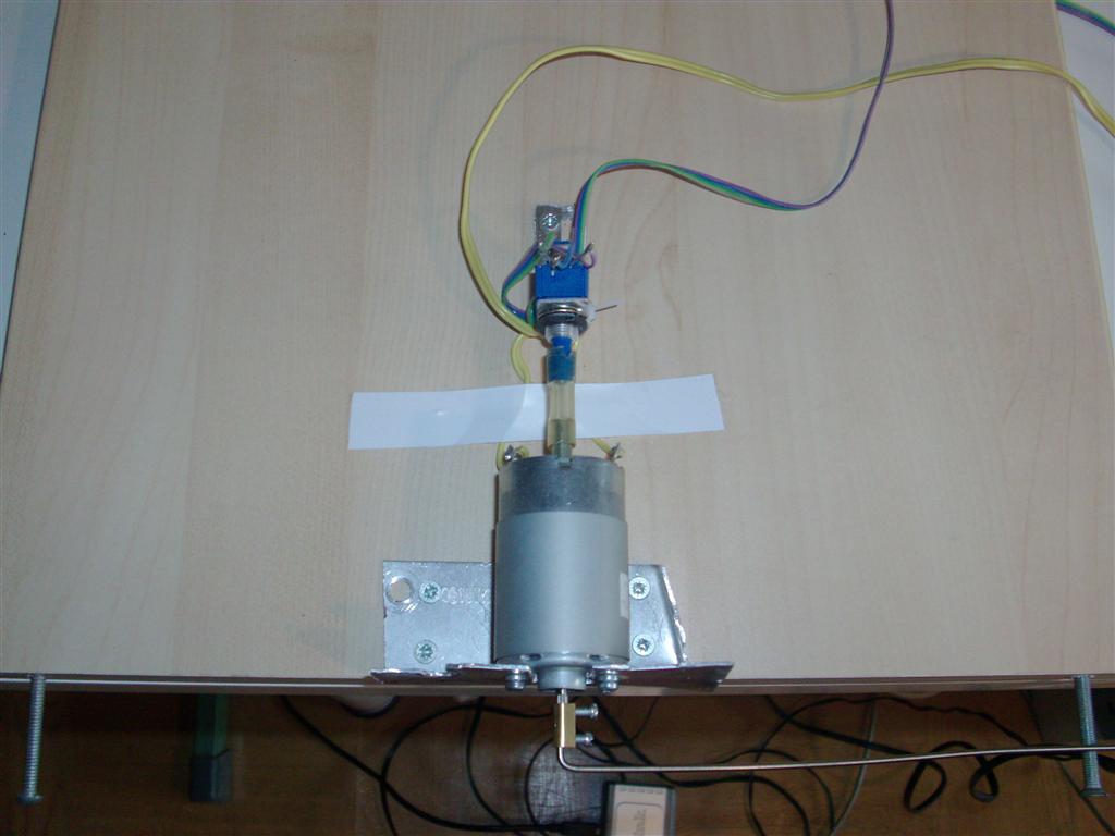
1. Overview of the project with the pendulum standing straight up.
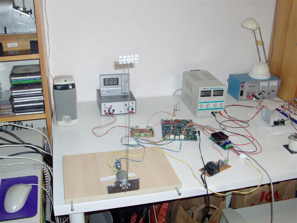
2. The DC-motor with 10 kOhm potentiometer as angular actuator and the axis
connection to the pendulum arm.
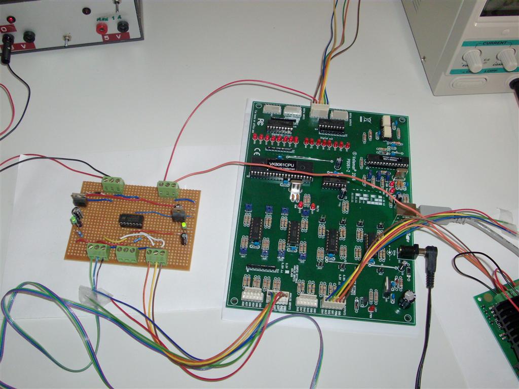
3. The Velleman K8061 I/O-board and the small auxiliary I/O interface board
with operational amplifier followers for the actuators.
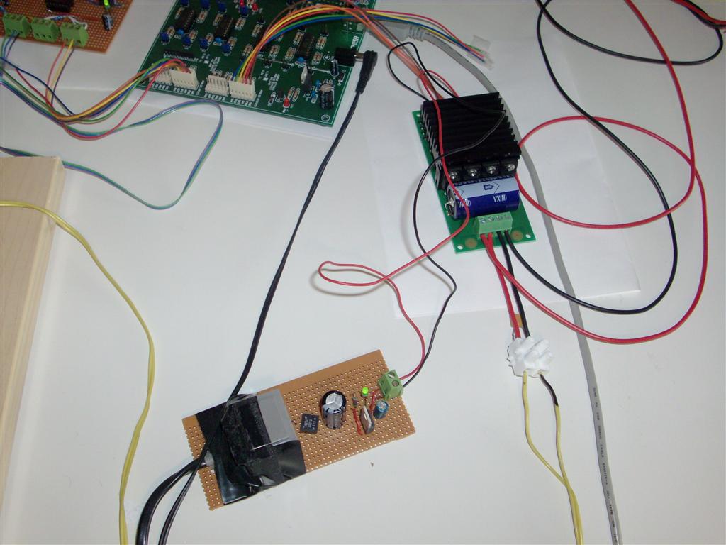
4. The Devantech MD03 motor controller with a small auxiliary +5 V, 50 mA
power supply for the small signal part.
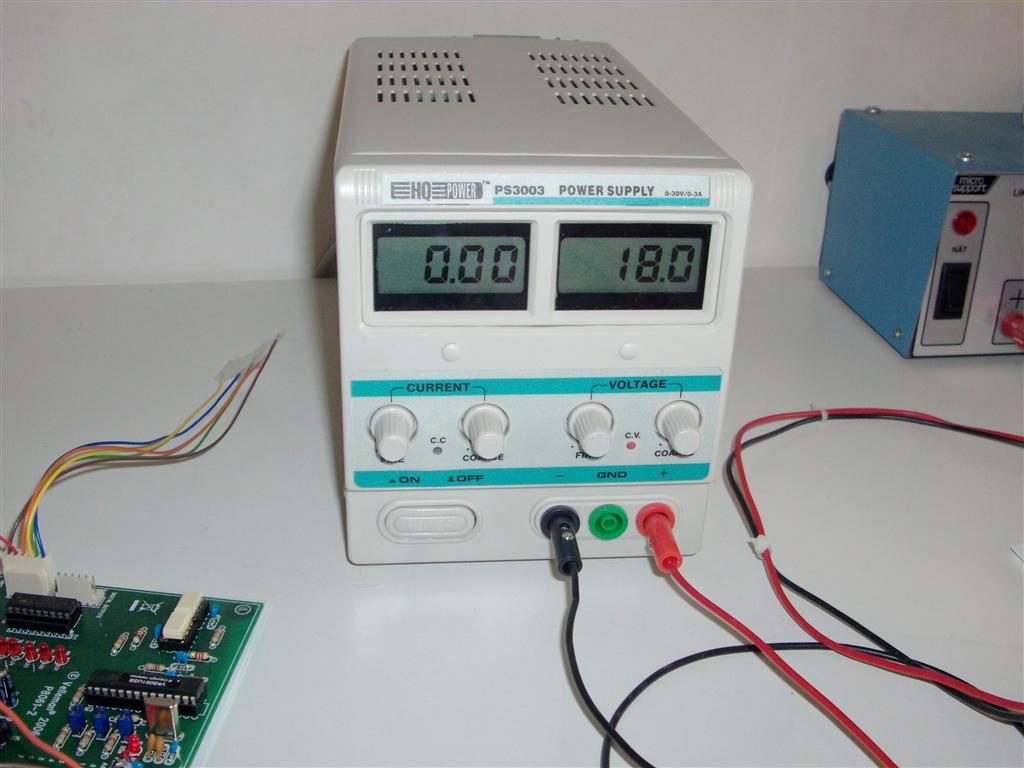
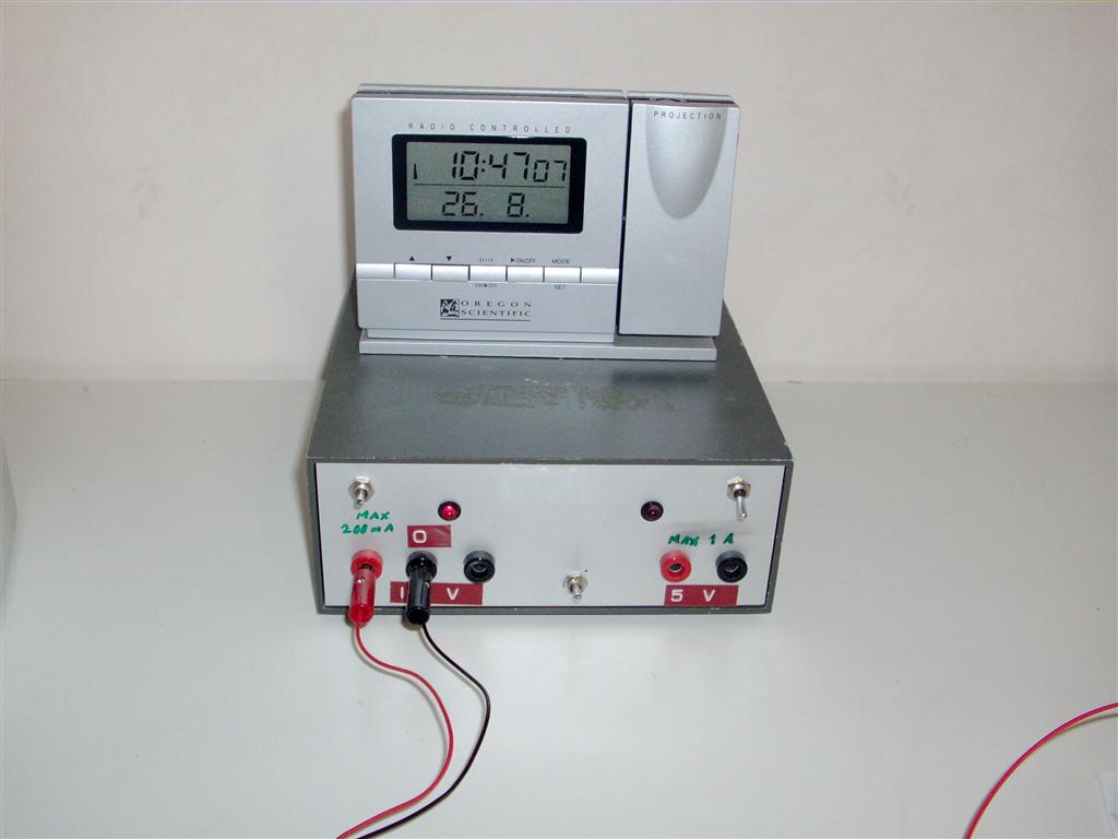
5. The main motor power supply here adjusted to 18 V (max 3 A).
6. A smaller 15 V power supply connected to the 7805 and 7809 voltage
regulators of the small auxiliary I/O interface board. And a radio controlled
digital clock on top.
7. A not so good image of the output of the PID-regulator program on the screen.
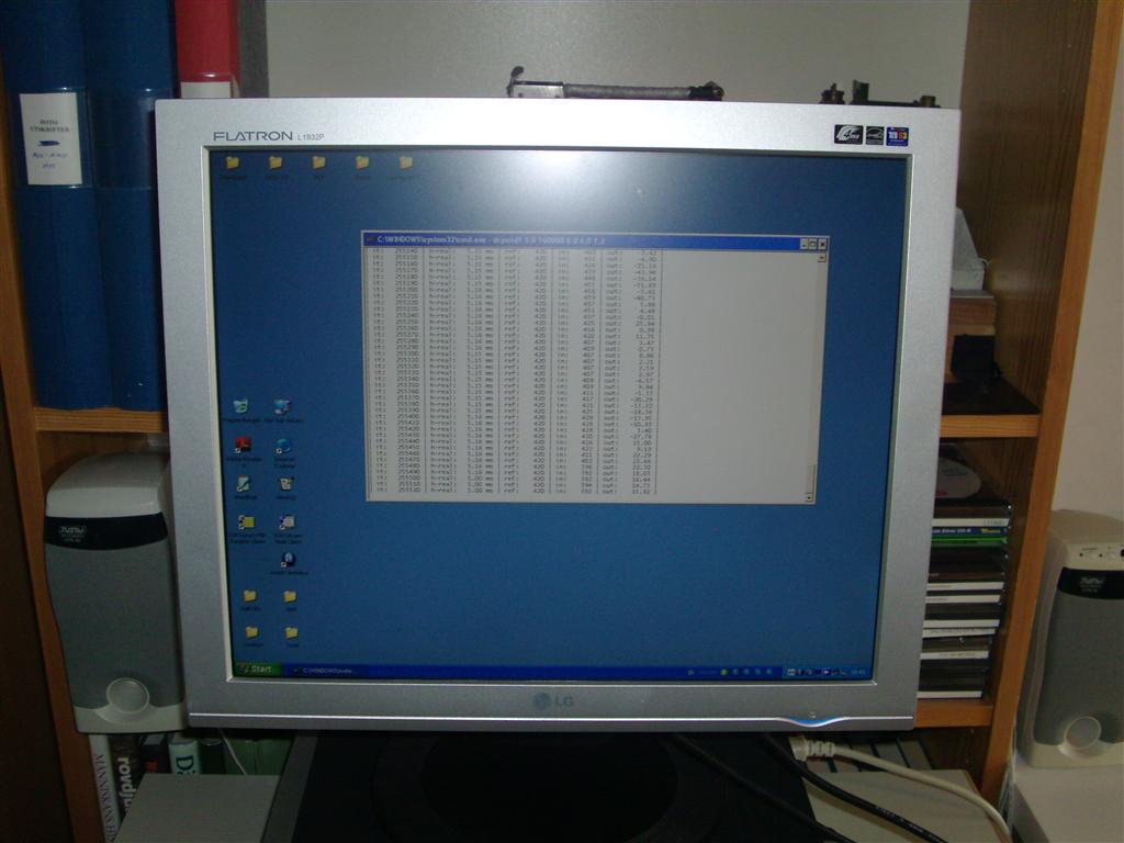
First the pendulum is balancing for itself. It oscillates quite a bit due to
limitations in the PID-regulator and perhaps non optimal settings. Then the
reference direction (angle) for the pendulum is changed from the computer
keyboard. Finally the pendulum arm is pushed by a metal bar and finds the
upright position again after some oscillations.
Some useful data sheets (mostly from ELFA) to download:
Some useful Internet links: