| A very good LED stroboscope (based on Elektor.com July 2012) |
|
Back to Stefan's Some technical projects page
Report by Stefan Spännare, January 30 2016
This LED stroboscope is based on an article found at Elektor.com July 2012. However
some changes are made. I do not have copy right to this article so I still hope you can buy
and download it from Elektor.com? Otherwhise contact me by mail for a scanned version.
i. Warning
1. Changes and construction of the LED stroboscope
2. Some photos of the LED stroboscope
3. A photo and a video when the LED strobe is "freezing" the rotation of a small fan
4. Some oscilloscope views of the LED stroboscope pulses
5. References
The author makes no warranties that this document is free of errors. Be careful to
avoid short circuit, solder carefully and use high quality components.
As mentioned this very good LED stroboscope is based on an article at Elektor.com July
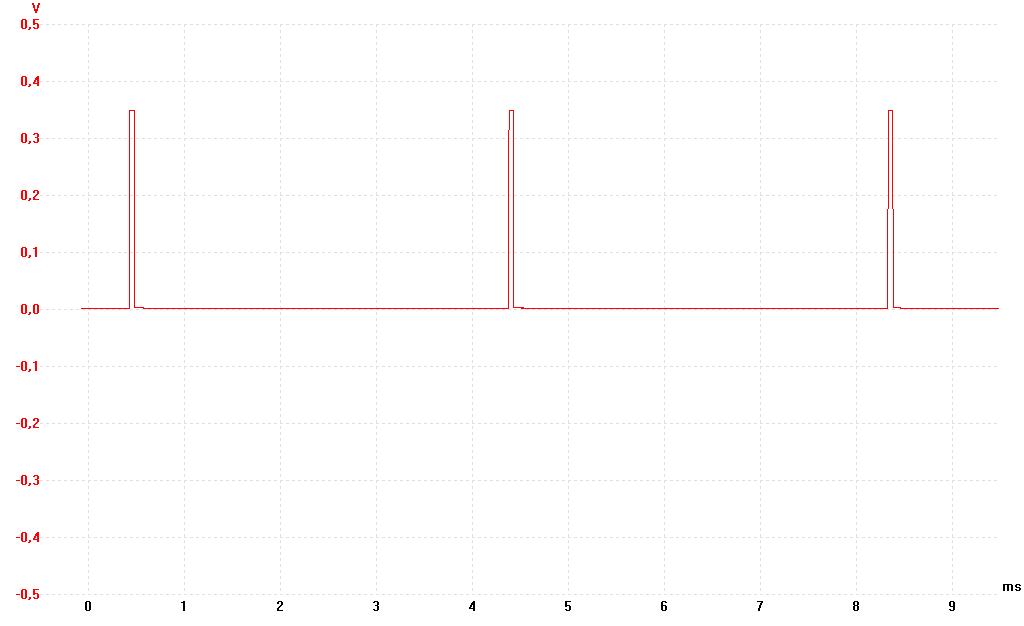
2012 but a few changes are made to slow down the flash frequency to 7 to 250 Hz. The
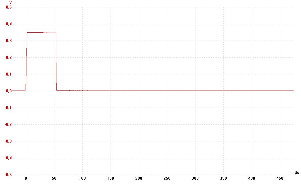
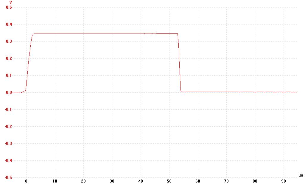
pulses are only about 55 μs long and almost perfect square waves. Thus very fast mechan-
ical movements (for example rotating machines, vibrations and pulsating speakers etc)
can be "frozen". I use a 16 V DC stabilised mains adapter and four 10 W power LEDs
connected to the circuit in series with 1 Ohm, 2 W inductance free metal film resistor
each. It works very well and makes the LED strobe relativley bright. The LEDs are
cold white at about 5900 K and need no heatsinks at these short pulses.
The PCB can be bought from the Elektor.com web shop, but I soldered the circuit on a
standard laboration card. To get the lower pulse frequency range only a few changes
must be made. I thought a speaker to hear the pulses was not nescessary so I omitted
LS1, S2, T2 and R10. Then just replace the potentiometer P1 with a linear one at
1 MOhm and the resistor R11 with 27 kOhm. Thats it. All other components can be
as they are described in the article. At the 16 V DC mains adapter input of the LED
strobe I also added a large capacitor of 2200 μF, 50 V that also acts as a holder for
the cables. See the images below.
Note that the TLC556 timer IC survives only up to 18 V DC. The switching power
MOSFET (IRLU024NPbF) can handle up to 55 V and 17 A I think. So by a separate
power supply for the LED itself also higher voltage and current power LEDs can be
used. The LED strobe circutit also works well at 4.8 to 6.0 V DC if you want it battery
operated. Then smaller 3 W LEDs at about 3 V can be conneced to it in series with
1 Ohm, 2 W metal film resistors. Because the pulses are so short the whole LED
strobe circuit (including the LEDs) drew only a few mA current when operated.
Important note. Perhaps you want to measure the pulse frequency of the LED
stroboscope with a quite slow frequency counter or multimeter? Then perhaps
the 55 μs pulses are to short for it? Instead connect the instrument between the
cathode side of the diode D1 (1N4148) and ground. There the pulses are much
longer and seem to have an almost 50/50 % duty cycle.
Four images with my digital camera. Image 4 is without camera flash so the LED
stroboscope flashes are cleraly seen. Unfortunately this image is not so sharp.
Click on the small images to make them large.
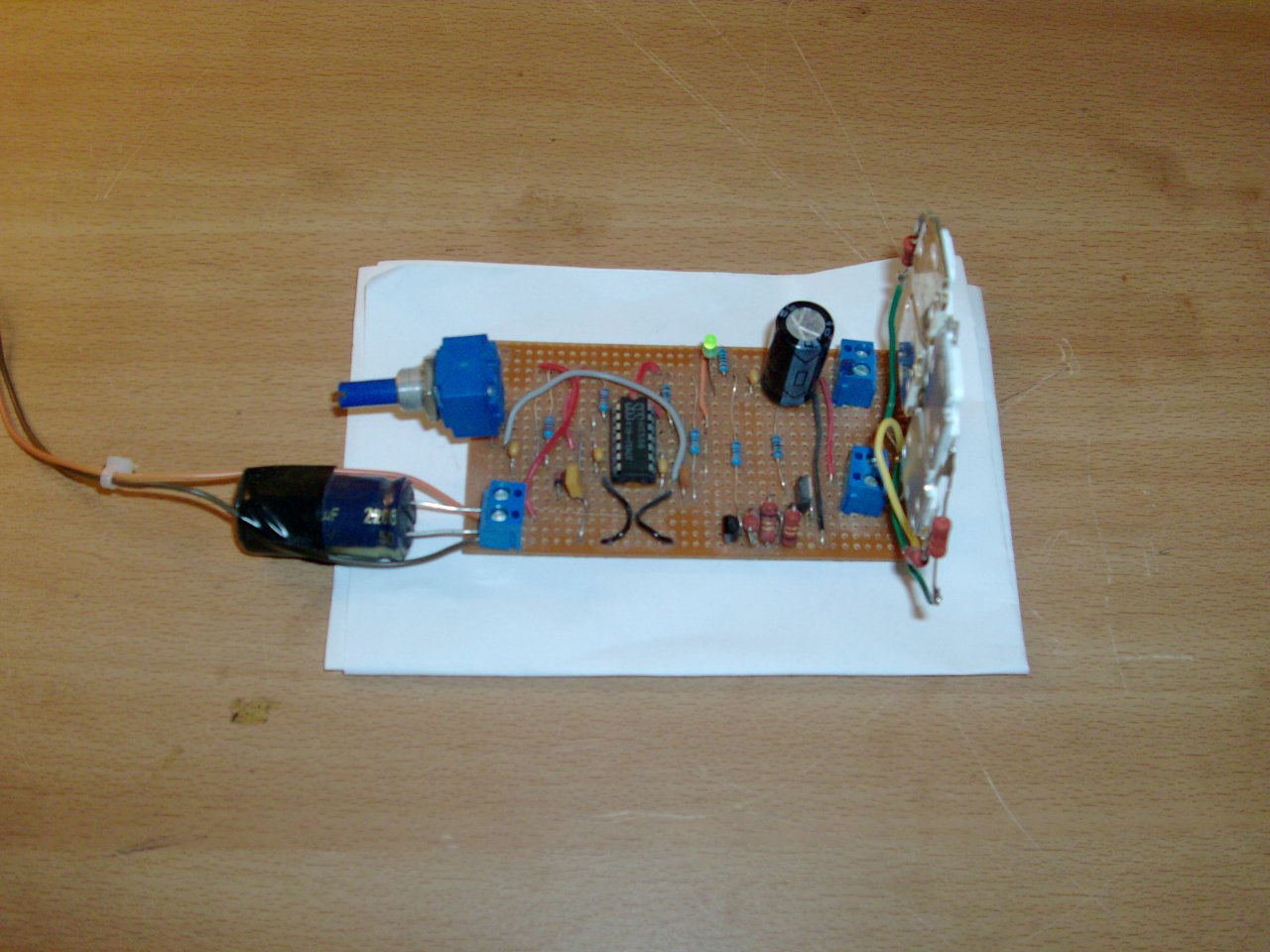


An image of the four power LEDs at 3 W, 3 V for battery operated mode of the LED
strobe at 4.8 to 6.0 V DC. I see that a 10 Ohm, 2 W metal film resistor is used in
series with each LED here. Probably 1 Ohm resistors also works well and give
somewhat brighter flashes.

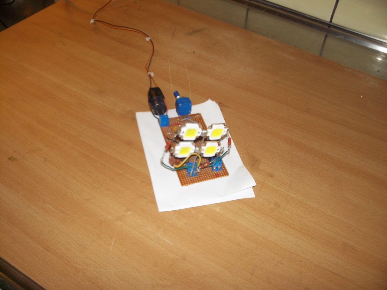
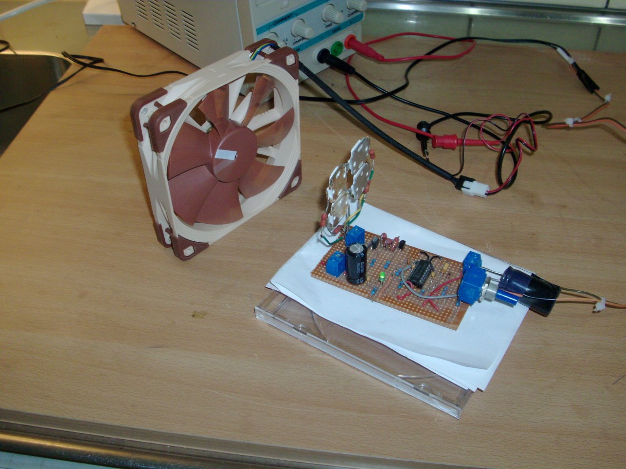
Here is an image of the setup when the LED stroboscope is "freeezing" the rotation of
a small fan.
A short video of a rotating fan almost "freezed" by the LED stroboscope. The rotation
of the fan and the strobe pulses are not exactly syncronized so one sees that someting
happens. Because of the short and not so bright strobe pulses and limitations of the CCD
of the digital camera the video quality is not so good. Video resolution 640 x 480
pixels I think.
ledstrobevid1.mp4 (4.09 MB, about 30 seconds long)
Three oscilloscope views of the about 55 μs flash pulses of the LED stroboscope here
measured over one of the 1 Ohm, 2 W metal film resistors in series with one of the
LEDs. The current is about 0.5 A so I think it was with 3 W, 3 V LEDs when the
stroboscope was operated at about 5.0 V DC? Click on the images to make them
two times larger.
Elektor.com (LED stroboscope article July 2012)
ELFA A nice electronics component shop in Sweden
If you want data sheets for the components of the LED stroboscope just Google on their
names and add "data sheet" when you search. They were bought from ELFA in Sweden.
I think the total cost was about $ 12 (excluding delivery costs and the power LEDs).
Data for the 10 W LEDs
I bought them new on Tradera.com in Sweden for about $ 2 each.
LED cold white
VF: 9 - 12 V DC
IFmax: 1000 mA
LM: 900 - 1000 lm
Color temp: 5900 K
Size: 20 x 29 mm (including solder ears etc)
Life span: > 50000 h
Author: Stefan Spännare