|
Power supply 13.8 V 4.4 A stabilized
with over voltage protection |
Back to Stefan's Some technical projects page
Report by Stefan Spännare, May 2008, updated June 2008
This project is based on information found on Internet.
Note, print this web-page in landscape mode if the images don't fit into portrait A4.
i. Warning
1. Credit and circuit layout
2. Introduction
3. Power supply data
4. Differences from the original circuit layout
5. Electronic component data
6. Over voltage protection
New!
7. Some images (photos) of the power supply
8. References
The author makes no warranties that this document is free of errors.
i. Warning
All credit to this project should go to "N1HFX" at the R.A.S.O.N. web-pages!
1. Credit and circuit layout
Many thanks to them! There is found a good circuit layout and some more
information. Here is the link:
The author needed a reasonable powerful (> 4 A) power supply at 13.8 V to
test some car stereo amplifiers. This time he made life easy and searched on
Internet for suitable schematics. He also happens to have a toroid trafo 80 VA,
2 x 18 V, some 2N3055 transistors and two large capacitors (10000 uF, 40 V)
at hand. He also likes constructions with the old but good LM 723 variable
voltage regulator.
Here are presented some data for the power supply.
| Voltage range: | 11.6 - 14.6 V (13.8 V default) |
| Max current: |
4.4 A
|
| Current limitation: | 6.5 A |
| Max voltage drift: | 30 mV |
| Max ripple: | 10 mV |
| Max power dissipation: | 120 W (with heatsink) |
| Fuse, DC output: | Not present |
| Fuse, mains voltage: | 1 A (slow) |
| Mains voltage: | 220 - 230 V, 50 Hz |
The components are not so critical. Here are presented the main differences
between the original circuit layout by "N1HFX" (13.8 V, 10 A) and the author
(13.8 V, 4.4 A). The 2N 3055 and BC 243 C transistors must have a quite
large heatsink. The author added a 200 Ohm, 4 W resistor at the power
output to make up a small idle load. He also added two capacitors of 47 uF,
40 V and 100 nF, 50 V at the LM 723 circuit board. To reduce the current
limitation to about 6.5 A the two 0.15 Ohm, 10 W resistors were replaced
with four resistors of 0.56 Ohm, 5 W connected in parallel.
| Circuit by N1HFX | Circuit by the author |
| Toroid trafo 200 VA, 2 x 18 V | Toroid trafo 80 VA, 2 x 18 V |
| Rectifier RS276-1185 | Rectifier 200 V, 25 A |
| 4 x 4700 uF, 35 V | 2 x 10000 uF, 40 V |
| TIP 3055 T | BD 243 C |
| 2 x 0.1 Ohm, 10 W | 2 x 0.1 Ohm, 5 W |
| 2 x 0.15 Ohm, 10 W | 4 x 0.56 Ohm, 5 W |
Here are presented some data (absolute maximum ratings) and approximate
prices for the most critical components in the power supply. Imax and Pmax
are given with appropriate heatsinks. Toroid trafos and large heatsinks are
quite expensive. The components can preferably be bought from the company
ELFA in Sweden (see the references).
| Component | Umax (V) | Imax (A) | Pmax (W) | Price ($) |
| Transistor 2N 3055 | 60 | 15 | 115 | 2 |
| Transistor BD 243 C | 100 | 6 | 65 | 1 |
| Rectifier 25 A | 200 | 25 | 50 | 3 |
| Resistor 0.1 Ohm | 0.71 | 7.1 | 5 | 1 |
| Resistor 0.56 Ohm | 1.67 | 3.0 | 5 | 1 |
| Voltage regulator LM 723 | 40 | 0.15 | 0.6 | 1 |
If driving valuable equipment (car amplifiers, radio equipment etc) from the
13.8 V power supply it is a good idea to have an over voltage protection. It
simply short circuits the power supply with a thyristor, so the fuse is
broken, if the voltage goes over about 15 V. This can happen if there is
something wrong with the regulator part of the power supply.
The over voltage protection shown here is a slightly improved version of
the one found on the web-page "High Current 13.8V Power Supply" (see
the references). The gate trigger current of the thyristor is typical 3 mA
(but can be as large as 32 mA) so the final short circuit voltage can vary
somewhat. This can be adjusted to about 15 V by adding or removing one
of the 1N4004 diodes. The voltage drop over each 1N4004 is about 0.7 V and
about 4.7 V over each Zener diode. Test the circuit with a variable voltage
and current limited power supply in the interval 12 to 17 V. The author's
circuit happens to short circuit at about 15.2 V, which is good. Equipment
to use with car lead accumulators usually survive up to 16 V.
The BT152-400R thyristor can handle 20 A continuously and up to 200 A for
10 ms and must have a small heatsink. It must be able to survive the short
circuit current the short time until the fuse is broken. Do not use a fuse
of more than 20 A with this circuit. The fuse should be fast and have
a value smaller than the current limitation of the 13.8 V power supply.
With the author's power supply a 4 A fast fuse is suitable because the
maximum allowed current is 4.4 A and the current limitation 6.5 A.
The price of the BT152-400R thyristor is about $ 5.
Over voltage protection circuit layout (modified by the author):
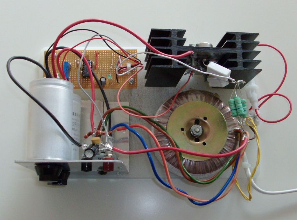
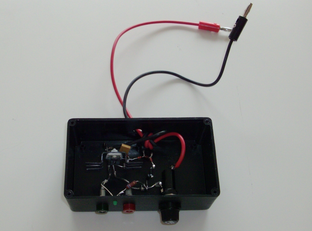
Here are presented some images (photos) of the power supply.
1. Power supply front view.
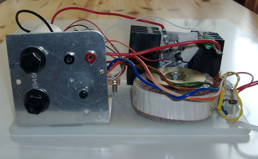
2. Power supply back view.
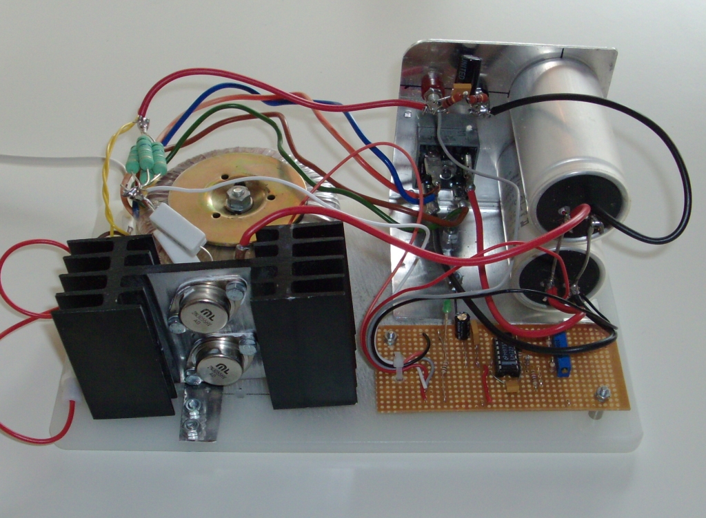
3. Power supply view from above.
4. The over voltage protection circuit. Note the small heatsink on the thyristor.
Some useful data sheets (mostly from ELFA) to download:
Some useful Internet links: