These images were taken with a Pico Technology ADC-212/3 oscilloscope for PC.
The current was measured by measuring the voltage over a 0.1 Ohm, 10 W thread
winded resistor, which probably also has some inductance. The resistor was
connected in series with the motor. The operating voltage was 24 V powered
from a large power supply which can handle a maximum average current of 15 A.
PI-regulator 1 and the improved MOSFET PWM-driver 1 with the 40EPF04 power
diode were used. The improved power converter was used. I.e. both the motor
and generator were EleGo 1/2 motors (24 V, 280 W, 2750 rpm). Load for the
generator was two car lamps (12 V, 55 W) connected in series.
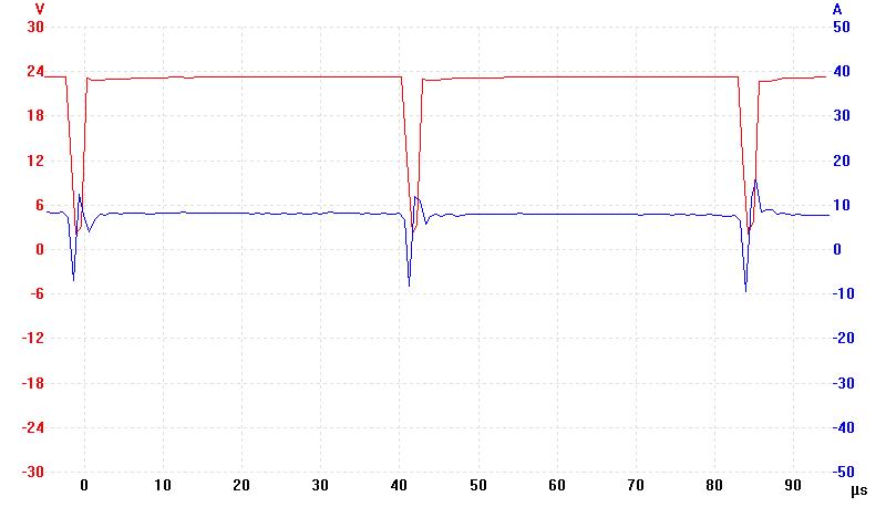
The PWM frequency from the Velleman K8055 I/O-board is 23437.5 Hz to be
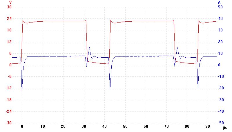
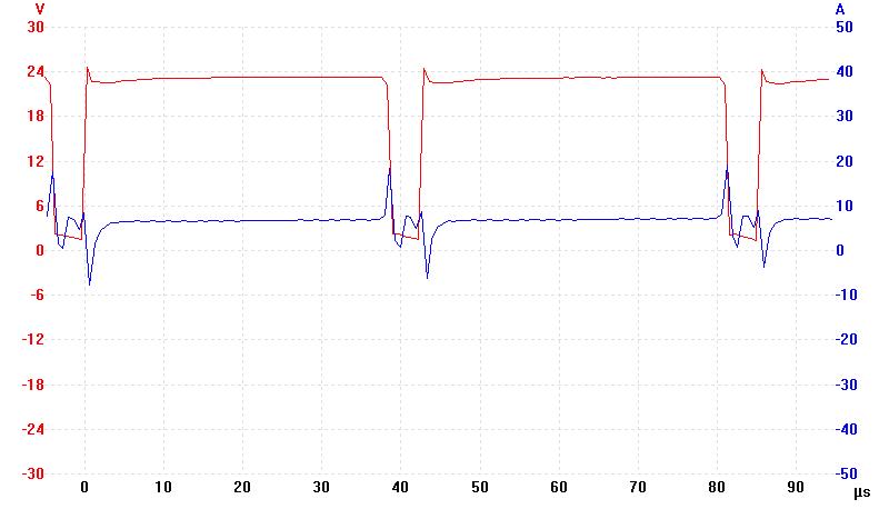
exact. Red curve is voltage over the motor and blue curve is current over
the motor (i.e. the 0.1 Ohm resistor). The size of the current spikes can
vary a lot between different oscilloscope frames at the same duty cycle and
load. The duty cycle corresponds to the "out" output from the PI-regulator.
1. PWM pulse over DC motor at 23.5 kHz and 5 % duty cycle.
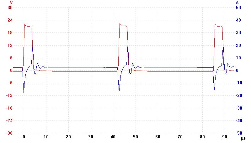
2. PWM pulse over DC motor at 23.5 kHz and 15 % duty cycle.
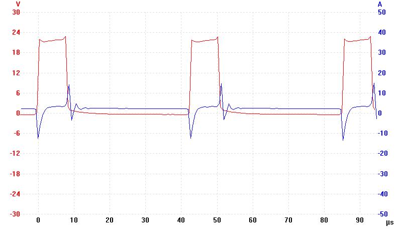
3. PWM pulse over DC motor at 23.5 kHz and 30 % duty cycle.
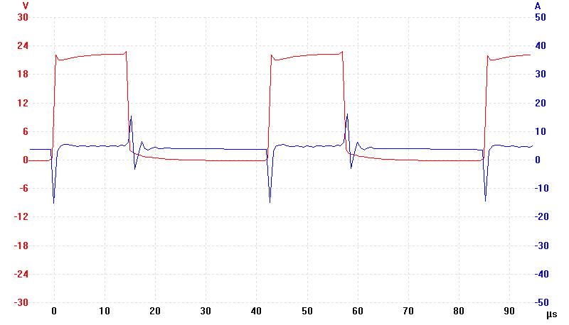
4. PWM pulse over DC motor at 23.5 kHz and 50 % duty cycle.
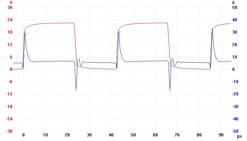
5. PWM pulse over DC motor at 23.5 kHz and 70 % duty cycle.
6. PWM pulse over DC motor at 23.5 kHz and 85 % duty cycle.
7. PWM pulse over DC motor at 23.5 kHz and 95 % duty cycle.