software for electric DC motors
|
Digital PWM-drivers and PI-regulator
software for electric DC motors |
 |
Back to Stefan's Some technical projects page
Report by Stefan Spännare, July 2004, updated March, October 2006, May, June 2007,
January and November 2008
See important notes and additions in section 4.3, 6.2, 6.3, 10, 11 and 12!
Note, print this web-page in landscape mode if the images don't fit into portrait A4.
These free digital PWM-drivers and PI-regulator software for electric DC motors are
based on information found elsewhere on Internet. See the references below.
i. Warning
1. Introduction
2. Switching theory
3. Computer controlled PI-regulators for DC motor speed control with feedback
3.1 Download PI-regulator software for Velleman K8055 and K8061 I/O-boards
Updated!
4. Some auxiliary circuits
4.1 +12 V voltage regulator
4.2 Feedback generator amplifier
4.3 Power MOSFET driver
5. PWM-driver 1
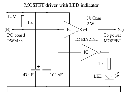
5.1 MOSFET driver
6. PWM-driver 2
6.1 Building instructions
6.2 Digital PWM-pulse generator
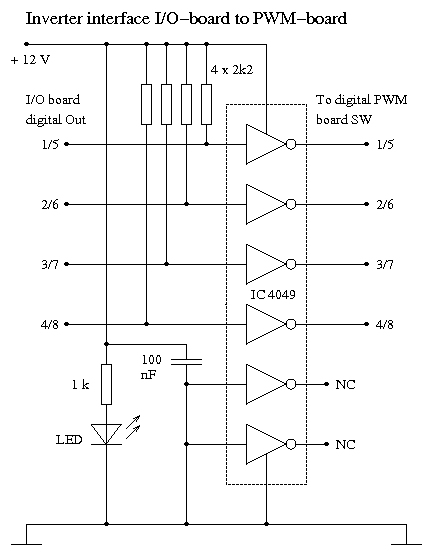
6.3 Inverter interface for Velleman K8055 and K8061 I/O-boards
Updated!
6.4 MOSFET driver
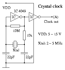
6.5 Crystal clock (2 - 5 MHz)
6.6 NE555 based clock up to 500 kHz
7. Electronic component data and prices
8. A comparison between Velleman K8055 and K8061 I/O-boards
Updated!
9. Some old images (photos) of the project
10. An improved power converter and MOSFET driver
Updated!
11. Some images (photos) of the improved project (K8055)
12. Some images (photos) of the improved project (K8061)
13. Some oscilloscope views of the PWM signals
14. References
Updated!
The author makes no warranties that this document is free of errors.
See important notes and additions in section 4.3, 6.2, 6.3, 10, 11 and 12!
Do absolutely not use the USB devices, software and circuits described
If the feedback loop from the generator is broken the motor will immediately
The electric motors described here are very strong (more than 1/3 Hp) and
Be very careful if connecting these circuits to larger (lead) accumulators.
i. Warning
in this report for professional and continuous use. USB devices can quite
easily hang and the setup should be carefully monitored when used.
speed up to 100 %. This can be very dangerous.
have very high torque. Keep hands, hair, ties, children and pets away from
rotating parts.
Very high short circuit currents could be dangerous and destroy and burn
your circuits. It is highly recommended to first test the circuits with a current
limited power supply and a small motor. It is also recommended to have
a fuse of 10 or 15 A (slow) connected to the power supply or accumulators.
PWM (Pulse Width Modulation) is an efficient way to vary the speed and power
of electric DC motors. Here are described two digital PWM-drivers for up to 60 V
DC motors with a maximum current up to 80 A. The digital construction makes
it easy to control the PWM-drivers from a computer with I/O-ports or other digital
device.
With the PWM-drivers described in this report, a computer (PC) and this
PI-regulator (Proportional and Integrating regulator) software the speed
of a quite large DC motor can be regulated independently of the motor load
reasonably well. The PI-regulator software is operated from the computer
keyboard and a Velleman K8055 or K8061 USB I/O-board is used as interface
between the PWM-circuits and the computer.
The best switching conditions are when the switch frequency is much higher
than the dynamics of the motor. The motor should "think" that it is powered
from a true DC voltage. Due to different references the frequency must be at
least 5 times higher than the rotation speed of the motor. I.e. if the motor rotates
at 6000 rpm (100 rps) the frequency must be higher than 5 · 100 Hz = 500 Hz.
A theoretically better explanation is that switching frequency must be much higher
than 1/Ta where Ta = L/R is the electric time constant of the motor. Here L is
the inductance and R the inner resistance of the motor. For a typical DC motor
(200 W, 24 V) L = 1 mH and R = 0.5 Ohm. This again means that the frequency
must be much higher than 1/Ta = R/L = 0.5 / 0.001 Hz = 500 Hz. Usually a
frequency around 20 kHz is used. This also avoids noise from the motor in
the audio range.
With the PWM-drivers (1 or 2) described in this report, a computer (PC)
and this PI-regulator software (the programs "pireg1" or "pireg2") the speed
of a quite large DC motor can be regulated independently of the motor load
reasonably well. The PI-regulator software is operated from the computer
keyboard and a Velleman K8055 or K8061 USB I/O-board is used as interface
between the PWM-circuits and the computer.
The DC motors used in this project must be powered either from a powerful 24
V power supply (see the references) or two 12 V lead accumulators connected
in series. Be careful to not short circuit the setup (especially when using
accumulators).
It should be noted that these PWM-drivers and PI-regulator programs only
can give positive power signal to the motor. I.e. the motor can only rotate
in one direction and the circuit can not brake the motor if the speed is
too high. To make a true four-quadrant regulation possible small motors
can be connected in a so called H-bridge with bipolar transistors (see the
references). But this is more complicated and doesn't work for the large
motors and a MOSFET drivers used here.
It should also be noted that the K8055 I/O-board is not a very fast device
with a response time of about 20 ms per command. But this is sufficient for
this purpose. The PWM frequency of the counters on the K8055 board is as
high as 6.0000 MHz / 256 = 23437.5 Hz and for the K8061 board 16.0000 MHz /
1024 = 15625 Hz which is very good. The K8061 board is faster and has a
response time of about 4 ms per command.
To sense the speed of the main motor a small generator must be rotating on
the same axis to give a feedback voltage to the PI-regulator (i.e. to one
A/D-port of the K8055 or K8061 board). As generator a small DC motor can
be used, preferably with 5 or more rotor poles and a output voltage of less
than 5 V at maximum motor speed. Important note, if the feedback loop from
the generator is broken the main motor will immediately speed up to 100 %.
This can be very dangerous.
The by far easiest PI-regulator setup is to use PWM-driver 1 together with the
"pireg1" software. The PWM-driver 2 setup (which is more complicated) and the
"pireg2" software can then be ignored. On the other hand the PWM-driver 2 is
a stand alone PWM-driver which can be controlled from any digital I/O-device
(or DIP-switches) without the K8055 board and the PI-regulator function.
To work with the PI-regulator software below the speed feedback generator
should be connected to A/D-port A1 of the K8055 board (preferably via the
amplifier described in section 4.2). For PWM-driver 1 output PWM1 of the K8055
board should be connected to the MOSFET driver in section 5.1. For PWM-driver
2 the digital outputs O1 to O8 of the K8055 board should be connected
(in bit swaped order) to the switches (SW 1 to 8) of the digital PWM-pulse
generator board (section 6.2) via the inverter interface described in section 6.3.
The PI-regulator software code must be slightly modified if other I/O-ports
of the K8055 board should be used. How to program the K8055 board refer to
the documentation on Velleman homepage (see the references).
The same is valid for the K8061 board but the digital outputs should not be
connected in bit swaped order for PWM-driver 2 for this device.
3.1 Download PI-regulator software for Velleman K8055 and K8061 I/O-boards
The PI-regulator C-programs were compiled using the Borland C/C++ compiler
version 5.5.1 and auxiliary files (lib, dll etc) for the K8055 and K8061 I/O-boards
(downloaded from the Velleman homepage, see the references) are included in
the package.
Drivers for Windows Vista can be downloaded from the Velleman homepage
(see the references). Then the software must be recompiled.
Don't forget to read the readme file (included in the package) before using the
programs. More information is also given in the header of each C-program.
This and future updates of the package will only contain new software for the
the Velleman K8061 I/O-board. However old software (for K8055) is still there.
Here are described some auxiliary circuits to use together with the PWM-driver
circuits and PI-regulator software.
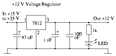
The small current parts of the PWM-drivers and auxiliary circuits (not the
motor itself) could be powered from a +12 V voltage regulator. Then the
input voltage must be larger than +15 V. The regulator survives a current
of maximum 1 A with a heatsink. Circuit layout:
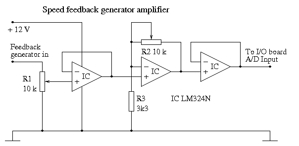
The output from the speed feedback generator (at full motor speed) can be
adjusted to 5.00 V with this amplifier to fit the K8055 or K8061 A/D input.
The potentiometers R1 and R2 can preferably be of 10 revolution trim types.
Circuit layout:
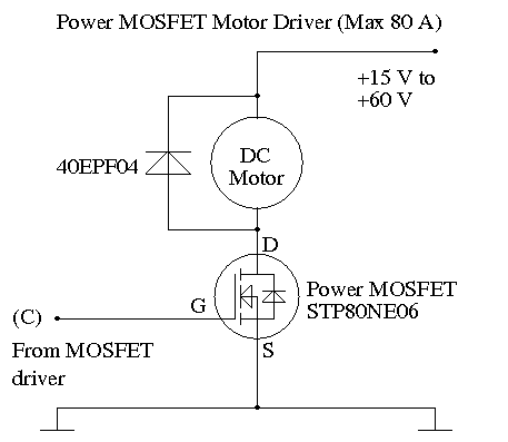
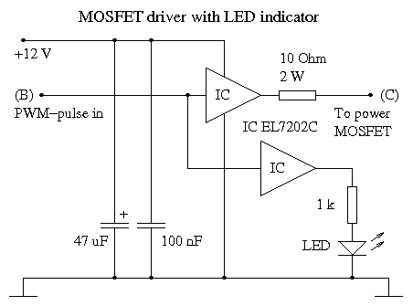
The MOSFET transistor in this motor driver requires a special driver circuit
(see section 5.1 and 6.4) between the PWM circuit and the MOSFET itself.
The reason for this is that switching the gate voltage of the MOSFET transistor
requires high transient current (2 A) due to relatively high capacitive load.
The MOSFET transistor and power diode must have relatively large heatsinks
for high current motors. A good article about MOSFET drivers is found on
Internet (see the references).
It is a good idea to have the power components (i.e. the MOSFET transistor and
the power diode) on a separate card with the heatsinks. See for example the
images (photos) below. The power components must be connected to the power
supply or accumulator and the motor with quite thick wires and cables. The
author use 1.5 mm (1.77 mm²) tin plated copper wires between the power
components and the cable connectors. This is probably enough for motors
that use a current of up to 20 A on average. The cables should also have an
area of at least 2 mm². For higher current motors the wires and cables must
be thicker accordingly. As pointed out in the warning it is very important
to not short circuit the setup, especially when connected to larger accumulators.
Always test with a current limited power supply and a small motor first to see
that everything works. It is also recommended to have a fuse of 10 or 15 A (slow)
connected to the power supply or accumulators.
The MOSFET must be protected from backward voltage and current by a power
diode. It is recommended to have a "fast recovery" rectifier (or switch) diode
for example 40EPF04. Such a diode survives 40 A on average and 400 A peak.
It has also a recovery time of only 60 ns and suppresses transients very fast.
This means that it dissipates very little heat in this application.
Circuit layout:
The simplest way to make a computer controlled PWM-driver is to use the
built in PWM-circuit on the K8055 or K8061 I/O-board. The PWM frequency
of the counters on the K8055 board is as high as 6.0000 MHz / 256 = 23437.5
Hz and for the K8061 board 16.0000 MHz / 1024 = 15625 Hz which is very
good. The circuit layout below show a simple but well working high current
motor interface using a power MOSFET transistor (see section 4.3) and this
dedicated MOSFET driver circuit.
MOSFET driver using a dedicated circuit (EL7212CN) as driver (see section
4.3 for the power motor MOSFET driver itself). Circuit layout:
In this section is described a more complicated but stand alone PWM-circuit.
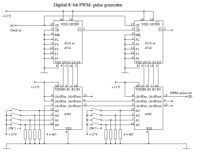
This digital PWM-driver is controlled by a 8-bit word from a computer with
I/O-ports or other digital device. Alternatively the word can be set by hand
with small DIP-switches. If controlled from a computer it is recommended to
use inverter buffers with open collector outputs as an interface to replace
the switches. Here two 4510 BCD counters are used meaning that the speed
of the motor can be varied from 0 to 100 % in 100 steps. Each counter has
4 bits each meaning that high and low bit sets must be counted "modulus 10"
if controlled from a 8-bit word. It is recommended to use a PWM-pulse at 20
kHz (see above) meaning that the counters must be clocked at 2 MHz. It is
possible to get higher speed control resolution by replacing one or both of
the 4510 by 4516. Then it is possible to get 160 or 256 speed steps instead.
To keep the PWM-pulse frequency at 20 kHz the counters must then be clocked
at 3.2 MHz or 5.12 MHz. Because the 4510, 4516 and 4585 CMOS circuits are not
so fast (working up to about 8 MHz at 12 V) the practical resolution will however
not be much higher with 256 steps than 100 steps. One possibility is to make
the clock frequency lower or use faster circuits. The 74LS series of circuits
are about 4 times faster but are powered from +5 V and corresponding circuits
do not have the same pin configuration as the CMOS ones (used in these layouts).
The circuits below can quite easily be built on a standard laboration card
(100 mm x 160 mm). It is recommended to connect a 100 nF capacitor between
+12 V and ground close to each digital IC. These capacitors are not included
in the circuit layouts. Depending on the desired PWM-pulse frequency it is
possible to use a crystal clock or a slower NE555 based clock. It is wise
to put all the ICs in sockets as well as the DIP-switches. The socket for the
DIP-swithes can also work as a cable connector from a computer I/O-ports.
The digital PWM-pulse generator. The switches (SW 1 - 8) control the PWM
pulse width (0 to 100 %). Open switch (low) means logical 0 and closed switch
(high) means logical 1. Circuit layout:
Important note, the connections for the K8061 board should be connected in
direct order but the connections for the K8055 board should be connected in
bit swaped order!
Two units are required for the 8-bit word. Note the swaped order of the connections
for the K8055 board. Bit 1 of the K8055 board should be connected to bit 8 of
the PWM-pulse generator board, bit 2 to bit 7 and so on. This is because bit
8 of the K8055 board goes high for a short while when the board "boots". To
avoid that the motor starts at 50 % speed the outputs are swaped giving the
motor only 1 % power when bit 8 is on. This is not the case for the K8061
board. It should be connected in direct order. Circuit layout:
MOSFET driver using a dedicated circuit (EL7202CN) as driver (see section
4.3 for the power motor MOSFET driver itself). Circuit layout:
Crystal clock (2 - 5 MHz). Circuit layout:
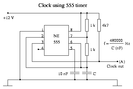
NE555 based clock up to 500 kHz. Circuit layout:
The main DC motor (24 V, 280 W, 2750 rpm) in this project comes as a spare part
for an electric scooter (EleGo 1/2). It can be bought from EleBike Center AB
in Sweden (see the references) and the price is about $ 50 plus delivery costs.
The Velleman K8055 I/O-board can be bought in most electronics shops and
the price is about $ 50. The price for the K8061 I/O board is about $ 100.
They can be bought from for example Kjell & Company in Sweden (see the
references).
Here are presented some data (absolute maximum ratings) and approximate
prices for the most critical and expensive components in the circuit layouts
above. Maximum average data for power components (i.e. Imax and Pmax) are
given with appropriate heatsinks and the components (at least the diodes) can
usually withstand up to ten times higher values for a short time (10 ms or so).
| Component | Umax (V) | Imax (A) | Pmax (W) | Ron (Ohm) | Price ($) |
| 4049 | 15 | - | - | - | 1 |
| 4510 | 15 | - | - | - | 2 |
| 4516 | 15 | - | - | - | 2 |
| 4585 | 15 | - | - | - | 2 |
| NE555 | 16 | 0.2 | 0.6 | - | 1 |
| LM324N | 32 | 0.05 | 0.5 | - | 1 |
| 7812 | 35 | 1 | 23 | - | 1 |
| EL7202CN / EL7212CN | 16.5 | 2 (< 2 μs) | 1 | - | 5 |
| STP80NE06 | 60 | 80 | 150 | 0.0085 | 5 |
| 40EPF04 | 400 | 40 | 40 | - | 5 |
| DS75-08B / DSI75-08B | 800 | 75 | 75 | - | 15 |
Here is presented a technical comparison between the Velleman (see the references)
K8055 and K8061 I/O-boards. How the PI-regulated power converter runs with the
two board is also briefly discussed below.
The K8055 board is quite easy to build (solder) but the K8061 board is more
complicated due to the many soldering points.
The PI-regulated power converter seems to run somewhat smother for the K8061
board than with the K8055 board. This is probably due to higher resolution in the
A/D-converter and PWM-output and the actual values varies in smaller steps. The
somewhat lower PWM-frequency for the K8061 board also has some influence.
It is also an advantage that the I/O-part for the K8061 board is isolated from the
computer. The K8061 board is a very fast device when USB 2.0 connected to a
reasonably fast computer (≥ 1.0 GHz). About 1.0 ms per I/O-operation can be
achieved.
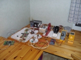
1. Overview of the project setup.
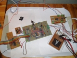
2. The main circuits described in this document. At center the PWM-driver 2
with crystal clock circuit and inverter interface (lower left). Upper right
the PWM-driver 1 and the feedback generator amplifier on the same board.
Lower right the power MOSFET with diode and cables.
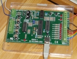
3. The Velleman K8055 I/O-board that works as interface between the
PWM-circuits and the main steering computer (not shown here).
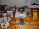
4. The power converter, two car lamps working as generator load and some
multimeters measuring generator voltage and current and the main motor
temperature.
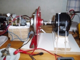
5. The PI-regulated power converter consists of the the main black DC motor
to the right (24 V, 280 W, 2750 rpm), a red pancake motor (with about the
same data but 6200 rpm at 24 V) which works as main load generator powering
two parallel connected car lamps (12 V, 55 W each) and to the left is the
small motor working as speed feedback generator.
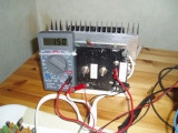
6. The main 24 V power supply (regulator part) and a multimeter measuring the
motor current.
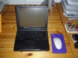
7. The old DELL Latitude XPi notebook computer working as oscilloscope viewer.
See also section 4.3 and the new images (photos) in section 11 and 12.
The power converter described above in this project is not so good because
the motor and generator have different characteristics. Of course this also
depends on the desired output voltage and current from the generator at a
certain rotation speed of the motor. For this project it is much better to
have a similar generator as the motor. The new power converter consists of
two EleGo 1/2 motors (24 V, 280 W, 2750 rpm). This means that the output
voltage from the generator is only slightly less than the input voltage of
the motor (somewhat dependent of the load of course). The efficiency η
of the power converter is about 50 % at 12 V and 57 % at 24 V. The load was
two car lamps (12 V, 55 W) connected in series.
It is also wise to take the feedback voltage directly from the generator power
output so the rotation speed is kept constant under different load. Then it
is very important to adjust the feedback voltage (with the potentiometers
on the feedback amplifier, see section 4.2) to not raise above 5.00 V at
full rotation speed, to not damage the A/D-converter of the Velleman K8055
or K8061 I/O-board.
If the load of the motor is not a generator in itself but for example a mechanical
device, the feedback voltage must be taken by a small auxiliary generator. As
feedback generator any small low voltage DC-motor with 5 poles (or more) on
the rotor should fit. The feedback generator should be connected to the same
axis as the main motor.
The MOSFET must be protected from backward voltage and current by a power
diode. It is recommended to have a "fast recovery" rectifier (or switch) diode
for example 40EPF04. Such a diode survives 40 A on average and 400 A peak.
It has also a recovery time of only 60 ns and suppresses transients very fast.
This means that it dissipates very little heat in this application.
Experiments show that temperature of the diode heatsink was slightly below
40 °C for the 40EPF04 diode and about as high as 70 °C for the DS75-08B
diode when the motor has been running at 30 % PWM duty cycle for about one
hour (i.e. steady state). Load for the generator was two car lamps (12 V, 55 W)
connected in series. The heatsink was a 60 mm KS88 with about 2.6 °C/W
(see ELFA homepage in the references). This means that the energy dissipation
for the 40EPF04 was about 6 W and for the the DS75-08B about 18 W at an
ambient temperature of about 23 °C. Thus use of the 40EPF04 makes the whole
system more energy efficient and it is also more lenient to the motor and
MOSFET due to faster transient suppression. The MOSFET (STP80EN06)
dissipates very little heat (less than 4 W) and the heatsink (a 40 mm KS88)
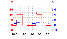
never becomes warmer than 40 °C. See also oscilloscope views of the
motor voltage and current in section 13.
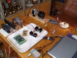
7. Overview 1 of the improved project setup with the Velleman K8055 I/O-board.
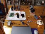
8. Overview 2 of the improved project setup with the Velleman K8055 I/O-board.
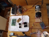
9. Overview 3 of the improved project setup with the Velleman K8055 I/O-board.
10. The Velleman K8055 I/O-board, PWM-driver 1 and the improved power MOSFET
driver with power diode and heatsinks.
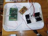
11. The improved power MOSFET driver. Both the MOSFET (STP80NE06) and
the power diode (DS75-08B) have large heatsinks. As mentioned in section 4.3
and 9 it is recommended to have a "fast recovery" rectifier (or switch) diode
for example 40EPF04 instead. Such a diode suppresses transients much faster
and dissipates much less heat. See also image 13.
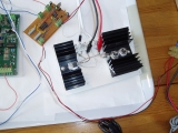
12. The improved power converter. The converter (motor and generator)
consists of the two EleGo 1/2 motors (24 V, 280 W, 2750 rpm) with the same
characteristics. The efficiency η of the power converter is about 50 %
at 12 V and 57 % at 24 V, somewhat dependent on the load, here two car
lamps (12 V, 55 W) connected in series.
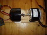
13. The new improved power MOSFET driver (left) with the 40EPF04 power diode
(right) and heatsinks.
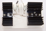
14. Overview 1 of the improved project setup with the Velleman K8061 I/O-board.
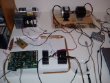
15. Overview 2 of the improved project setup with the Velleman K8061 I/O-board.
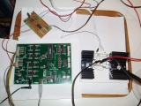
16. The Velleman K8061 I/O-board.
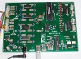
17. Another view of the improved power converter.
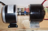
Click here to view this section.
PI-regulator theory (laboration exercise) to download:
Some useful data sheets (mostly from ELFA) to download:
Some useful Internet links: