at A 440 Hz
|
An electronic tuning fork
at A 440 Hz |
|
Back to Stefan's Some technical projects page
Report by Stefan Spännare, October 2004
Note, print this web-page in landscape mode if the images don't fit into portrait A4.
This free electronic tuning fork at A 440 Hz is based on information
found elsewhere on Internet. See the references below.
i. Warning
1. Introduction and data
2. About the construction
3. Building instructions
4. Crystal clock at 3.0000 MHz
5. The divide by 2 · 3409 circuit
6. Square wave to sinus wave filter
7. The +12 V voltage regulator
8. Some oscilloscope views of the sinus signal
9. Some images (photos) of the circuits
10. References
The author makes no warranties that this document is free of errors.
Be careful to avoid short circuit and use high quality components.
A tuning fork can be used to tune different music instruments to a certain
Theoretical frequency: 440.011734 Hz, (3.000000 MHz / (2 · 3409))
Practical frequency: 440.01 Hz +/- 0.03 Hz
Input voltage (VDD): 8 - 15 V
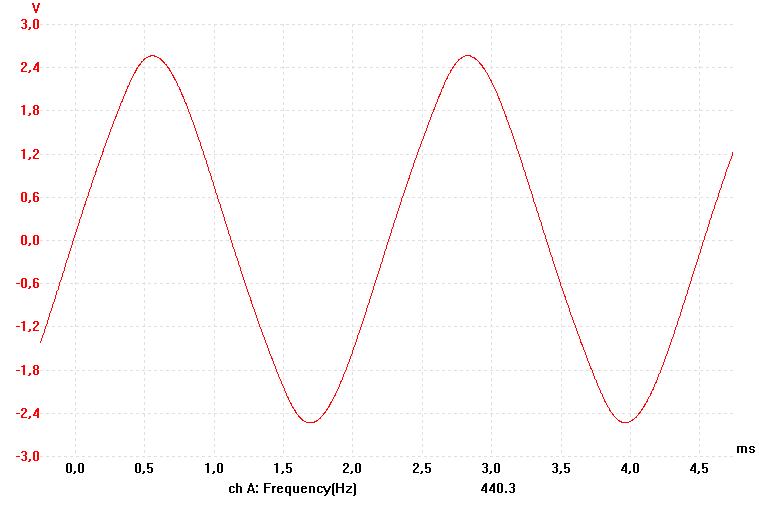
Sinus output: 0.20 · VDD V pp, (2.4 V pp at 12 V VDD)
Sinus output distortion (THD with noise): ~ 6 %
Maximum sinus output load: 2 mA, (1 kOhm)
Here 3.000000 MHz is divided by 2 · 3409 giving the theoretical frequency
The clock frequency can be fine tuned by a variable capacitor. Despite
The circuits below can quite easily be built on a standard laboration
Crystal clock at 3.0000 MHz. The frequency can be fine tuned by the
The divide by 2 · 3409 circuit. Circuit layout:
Square wave to sinus wave filter. Note, the filter is optimized for 440 Hz.
The +12 V voltage regulator. This circuit should be omitted if the tuning fork
These images are taken with a Pico Technology ADC-212/3 oscilloscope for PC.
1. The sinus output at 440 Hz and 12 V VDD.
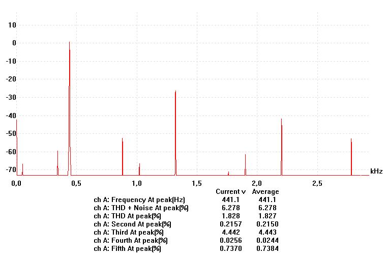
2. The spectrum of the sinus output at 440 Hz and 12 V VDD.
The scale of the y-axis is in Decibel (dB).
The complete electronic tuning fork. With crystal clock, divide by
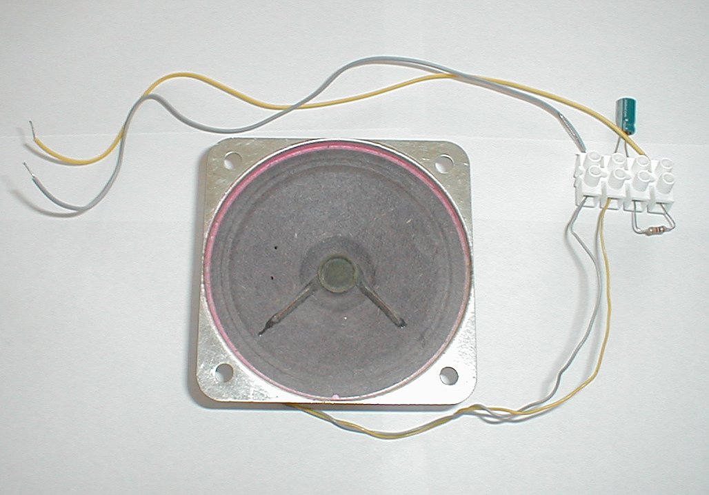
The small speaker (160 Ohm) with 1 uF filter capacitor.
Some useful data sheets (mostly from ELFA) to download:
Some useful Internet links:
i. Warning
1. Introduction and data
tone (usually A 440 Hz). The electronic tuning fork described here is much
more accurate in frequency than a mechanical tuning fork. The tuning fork
can easily be powered from a 9 V battery. It is also quite cheap to build
(about $ 10 in total). The sinus output at 440 Hz can be used to drive a
small speaker or ear-phones.
Data for the tuning fork:
2. About the construction
The idea to the divide circuit in this project comes from Henry's web-page
A440 test oscillator and much credit should be given to him. However the
construction here is slightly improved and has more exact frequency. The
construction of the square wave to sinus wave filter also differ.
440.011734 Hz. A 4049 inverter in the divide circuit is also needed to give
the clock pulses to the 4040 and 4013 circuits the same phase. Otherwise
the least significant bit of the 4040 doesn't work. This also means that
the number selected by the diodes should be 2 less than 3409.
that the author was not able to tune the clock circuit below 3.000138 MHz
(440.0309 Hz out and a measured divide factor of 2 · 3409.0083). This is
however less than the allowed manufacturing errors (50 ppm) of the crystal
and depends perhaps also on non optimum capacitor values in the clock
circuit. The frequencies were measured by a TTi TF830-RS232 Universal
Counter with 8 significant digits and reciprocal counting (see the references).
3. Building instructions
card (100 mm x 160 mm). It is recommended to connect a 100 nF capacitor
between VDD and ground close to each digital IC. These capacitors are
not included in the circuit layouts. All cables and copper paths close
to the crystal clock should be as short as possible.
4. Crystal clock at 3.0000 MHz
variable capacitor. Circuit layout:
5. The divide by 2 · 3409 circuit
6. Square wave to sinus wave filter
Circuit layout:
7. The +12 V voltage regulator
is operated from a 9 V battery (or less than 15 V). Circuit layout:
8. Some oscilloscope views of the sinus signal
The THD (Total Harmonic Distortion) with noise is about 6 %.
9. Some images (photos) of the circuits
2 x 3409 circuit, square wave to sinus wave filter and voltage regulator.

A 1 kOhm resistor limits the current to a few mA.
10. References
by Fairchild Semiconductor, January 1999
by Philips Semiconductors, January 1995
by National Semiconductors, February 1988
by Texas Instruments, February 1997
Author: Stefan Spännare
E-mail: stefan@NOspaennareSPAM.se
(Please remove NO and SPAM before sending)
Latest update: 2006-03-21